
Zinco Shear-Fix LF 600 for absorbing shear and tensile forces
Heavy-duty / extremely high loadable Connector made of solid stainless steel for installation in waterproofing / sealing pitched roofs according to the loose / fixed flange principle. Replaces shear sills in conjunction with the ZinCo Eaves Profiles.
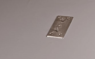
max. bearing capacity up to 600 kg/each; two-part, made of solid stainless steel, material thickness 5 mm each, surface trowalised, dimensions / measurement base plate 90 mm x 170 mm (fixed flange), dimensions / measurement holder made of solid stainless steel 60 mm x 140 mm, height 100 mm, incl. accessories and all screws for fastening in wooden substrate. Weight including screws approx. 1.6 kg. Fastening devices certified by construction supervision authorities for fixing to concrete are also available on request (concrete strength class min. C20/25).
| Order Nr.: | 9569 |
|---|---|
| Material: | Stainless steel 5 mm, surface trowalised |
| Length [mm]: | 140,0 |
| Width [mm]: | 60,0 |
| Height [mm]: | 100,0 |
| Packaging unit: | Piece |
| Weight [kg]: | 1,6 |
| Additional information: | Load bearing capacity: approx. 600 kg/connector; base plate: approx. 170 x 90 mm |
made of solid stainless steel in two parts, surface sandblasted, material thickness 5 mm each, dimensions / measurement base plate approx. 90 mm x 170 mm (fixed flange), dimensions / measurement holder made of solid stainless steel approx. 60 mm x 140 mm, height 100 mm, incl. accessories and screws for fastening in wooden substrates, weight approx. 1.6 kg/each incl. screws.
For securing the greening structure against slipping in conjunction with the Eaves Profile TRP 140 at the eaves or as a shear sill in the Area. Installation is carried out in the supporting structure with 5 corrosion-protected screws and is sealed using the loose fixed flange system in accordance with DIN 18195 with the waterproofing materials used on the building (waterproofing of the roof). Load bearing capacity 600 kg/Connector.
Fastening devices certified by construction supervision authorities for fixing to concrete are also available on request (concrete strength class min. C20/25).
Product: Zinco "Shear-Fix LF 600" shear fix bracket
Unit: pcs
Order Nr.: 9569
Scope of delivery:
1 base plate
1 Connector LF 300 or LF 600
2 M10 nuts (Stainless steel)
5 wood screws (galvanized steel)
2 EPDM spacers (1 large + 1 small)
1 bit
Preliminary remarks:
The installation of the Shear-Fix LF 300 and LF 600 is basically identical.
The installation and sealing of the base plate (fixed flange) varies slightly depending on the sealing material used. Work step 3 is therefore divided into waterproofing / sealing with bitumen and polymer bitumen membranes and waterproofing / sealing with plastic or elastomer membranes. Normally, installation is carried out on rafters made of solid wood, KVH (NH C24, S10 or higher) or similar suitable substrates.
The rafter width should be at least 100 mm (screw holes pre-drilled with D=5 mm, otherwise at least 140 mm). The base plate (fixed flange) is positioned in the center.
When installing in timber formwork or thick wood (e.g. Kerto or similar), the installer must procure suitable fasteners. The required material thickness of the shuttering depends on these fasteners.
The choice of fasteners must meet the requirement of a load of at least 6 kN for the Shear-Fix LF 600.
Notice:
The illustrations in these installation instructions are shown when fastening to the eaves. Irrespective of this, installation is also possible within the roof surface to create shear protection
Installation steps:
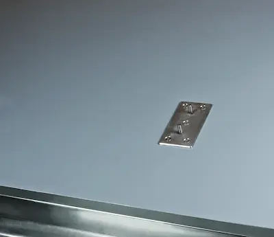
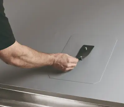
1. Measuring and marking the installation positions. In the case of bituminous waterproofing / sealing, the waterproofing membrane should be cut to the size of the base plate in order to avoid excessive elevation of the construction in the area of the base plate.
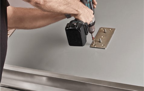
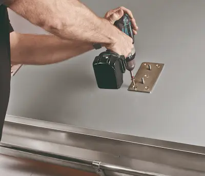
Screw the base plate in place
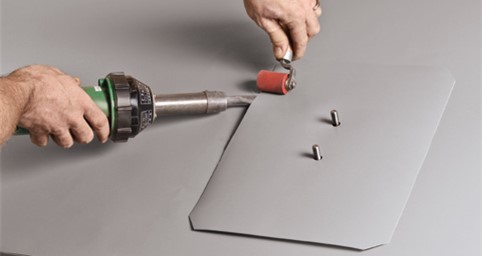
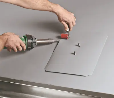
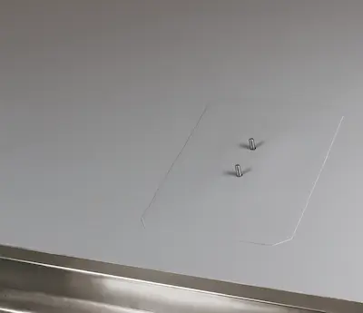
2. Properly install the base plate (fixed flange) at the marked position using the 5 wood screws supplied. Ensure that the screws are perpendicular to the base plate. Suitable bit inserts are included in the scope of delivery.
The screw holes should be pre-drilled to 5 mm.
Notice:
Contractor and installation in accordance with DIN 18195 and guidelines for flat roof construction. Only for use with non-pressing water in accordance with DIN 18195, DIN 18531 and guidelines for flat roof construction. For installation in concrete, use at least 4 Würth concrete screws W-BS/A4 Ø 6×65 anchors per base plate (5 for LF 600) or similar according to manufacturer's specifications.
3. Cut to size from the waterproofing membranes used.
Waterproofing of the roof with bitumen and polymer bitumen:
For waterproofing of the roof with bitumen and polymer bitumen membranes, at least two layers must be applied in accordance with the regulations. The overlap of the 1st layer must be at least 80 mm beyond the base plate; the 2nd layer must also be welded with at least 80 mm overlap beyond the 1st layer.
For single-layer bitumen waterproofing, proceed in accordance with the manufacturer's instructions. Mark the holes for the threaded bolts on the blanks and punch them out with a Ø 12 mm punch.
Notice:
The larger EPDM intermediate layer supplied is not required for bituminous waterproofing / sealing.
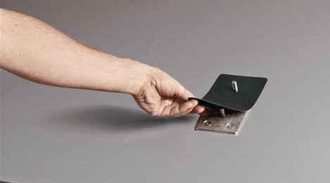
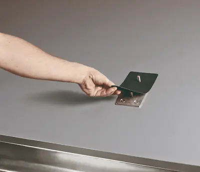
Plastic or elastomer membranes:
For waterproofing of the roof with plastic or elastomer membranes, place the large EPDM intermediate layer on the base plate. The size of the waterproofing membrane cut to size must be such that it can be professionally hand-welded over the EPDM interlayer in accordance with the manufacturer's instructions.
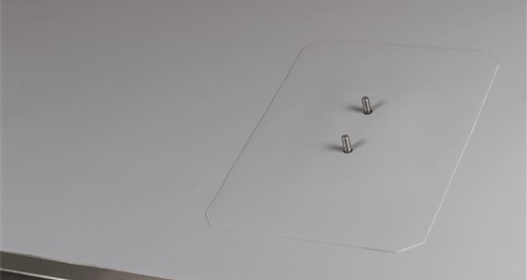
Mark the holes for the threaded bolts on the blanks and punch them out with a Ø 12 mm punch.
Notice:
No waterproofing membranes laminated with separating or protective fleece on the underside may be used.
Lay a larger EPDM intermediate layer
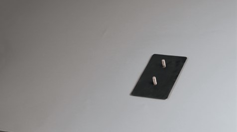
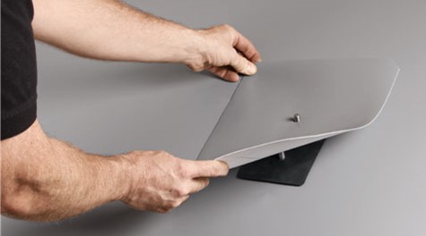
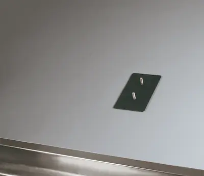
Perforated cutting of the waterproofing membrane
Professional welding of the cut to size
Lay small EPDM intermediate layer
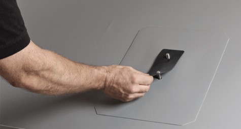
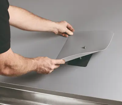
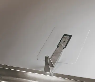
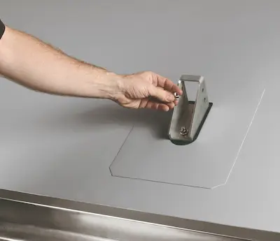
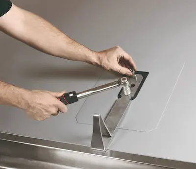
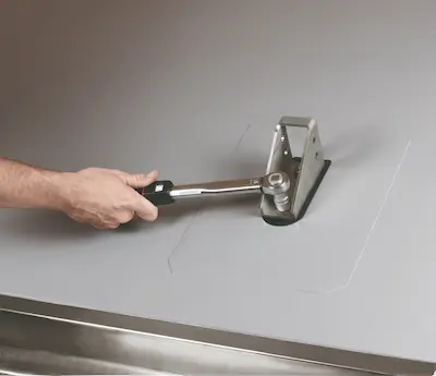
4. Place the shear holder (loose flange) over the threaded bolts and tighten evenly with the M10 nuts (wrench size 15 mm) alternately with a minimum of 20 to a maximum of 24 Nm. The use of a torque wrench is recommended to ensure the required tightening values.
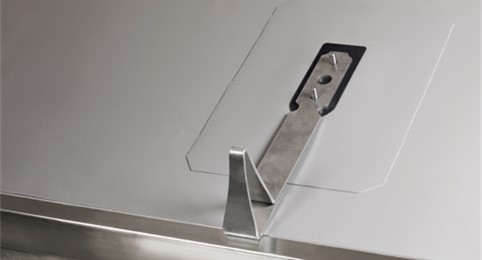
Shear-Fix LF 300 via threaded bolt
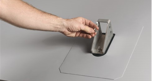
Insert Shear-Fix LF 600 via threaded bolt
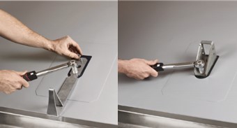
Tighten M10 nuts with 20 to max. 24 Nm
5. Check the tightness of the nuts twice over 24 hours and retighten if necessary.
6. Finally, check all weld seams of the sealing blanks and the tightness of the screw fixing.
1 Grundplatte
1 Halter LF 300 bzw. LF 600
2 Muttern M10 (jeweils Edelstahl)
5 Holzschrauben (verzinkter Stahl)
2 Zwischenlagen aus EPDM (1 groß + 1 klein)
1 Bit
Vorbemerkungen:
Der Einbau des Schubfix LF 300 und LF 600 ist grundsätzlich identisch. Der Einbau und die Eindichtung der Grundplatte (Festflansch) variiert je nach verwendetem Abdichtungsmaterial leicht. Arbeitsschritt 3 ist daher unterteilt in Abdichtungen mit Bitumen- und Polymerbitumenbahnen und Abdichtungen mit Kunststoff- oder Elastomerbahnen. Normalerweise erfolgt die Montage auf Sparren aus Vollholz, KVH (NH C24, S10 oder höherwertiger) o. ä. geeigneten Untergründen.
Die Sparrenbreite sollte mindestens 100 mm betragen (Schraublöcher vorgebohrt mit D=5 mm, sonst mind. 140 mm). Die Anordnung der Grundplatte (Festflansch) erfolgt mittig.
Bei Montage in Holzschalungen oder Dickholz (z. B. Kerto o. ä.) sind vom Verarbeiter geeignete Schraubmittel zu beschaffen. Die erforderliche Materialdicke der Schalungen ist abhängig von diesen Schraubmitteln.
Die Auswahl der Schraubmittel muss der Anforderung einer Belastung des Schubfix LF 300 von mind. 3 kN genügen.
Hinweis:
Die Abbildungen sind in dieser Montageanleitung bei Befestigung an der Traufe dargestellt. Unabhängig davon ist der Einbau auch innerhalb der Dachfläche möglich, um eine Schubsicherung herzustellen.
Einbauschritte:
1. Einmessen und kennzeichnen der Montagepositionen. Bei bituminöser Abdichtung sollte die Abdichtungsbahn in Größe der Grundplatte ausgeschnitten werden, um eine zu starke Erhöhung des Aufbaus im Bereich der Grundplatte zu vermeiden.
Grundplatte festschrauben
2. An gekennzeichneter Position Grundplatte (Festflansch) mit den 5 Stück mitgelieferten Holzschrauben fachgerecht montieren. Es ist darauf zu achten, dass die Schrauben rechtwinklig zur Grundplatte gesetzt werden. Passende Bit-Einsätze sind im Lieferumfang enthalten.
Hinweis:
Ausführung und Einbau in Anlehnung an DIN 18195 und Flachdachrichtlinie. Einsatz nur bei nichtdrückendem Wasser im Sinne DIN 18195, DIN 18531 und Flachdachrichtlinie. Für die Montage in Beton bauseits je Grundplatte mindestens 4 Stück (für LF 600 5 Stück) Anker Würth Betonschrauben W-BS/A4 Ø 6×65 oder vergleichbar nach Herstellerangaben verwenden.
3. Zuschnitte aus den verwendeten Abdichtungsbahnen herstellen.
Dachabdichtung mit Bitumen- und Polymerbitumen:
Bei Dachabdichtungen mit Bitumen- und Polymerbitumenbahnen sind regelgerecht mindestens zwei Lagen auszuführen. Die Überdeckung der 1. Lage muss mindestens 8 cm über die Grundplatte hinaus erfolgen; die 2. Lage ist ebenfalls mit mindestens 8 cm Überdeckung über die 1. Lage hinaus zu verschweißen. Bei einlagiger Bitumenabdichtung ist gemäß Herstellerangabe zu verfahren. Auf den Zuschnitten Lochungen für die Gewindebolzen anzeichnen und mit einem Locheisen Ø 12 mm ausstanzen.
Hinweis:
Bei bituminöser Abdichtung wird die mitgelieferte größere EPDM Zwischenlage nicht benötigt.
Kunststoff- oder Elastomerbahnen:
Bei Dachabdichtungen mit Kunststoff- oder Elastomerbahnen auf der Grundplatte die große Zwischenlage aus EPDM auflegen. Die Größe des Zuschnitts der Abdichtungsbahn ist so herzustellen, dass bei Überdeckung über die EPDM-Beilage hinaus eine Handverschweißung nach Herstellerangabe fachgerecht möglich ist. Auf den Zuschnitten Lochungen für die Gewindebolzen anzeichnen und mit einem Locheisen Ø 12 mm ausstanzen.
Hinweis:
Es dürfen keine unterseitig mit Trenn- oder Schutzvliesen kaschierte Abdichtungsbahnen verwendet werden.
Größere EPDM Zwischenlage auflegen
Gelochter Zuschnitt der Abdichtungsbahn
4. Schubhalter (Losflansch) über Gewindebolzen stecken und mit den Muttern M10 (Schlüsselweite 15 mm) gleichmäßig im Wechsel mit mind. 20 bis max. 24 Nm anziehen. Es wird die Verwendung eines Drehmomentschlüssels zur Sicherstellung der erforderlichen Anzugswerte empfohlen.
Schubfix LF 300 über Gewindebolzen
Schubfix LF 600 über Gewindebolzen stecken
M10-Muttern mit 20 bis max. 24 Nm anziehen
5. Über 24 Stunden den festen Sitz der Muttern zweimal prüfen und ggf. nachziehen.
6. Zum Schluss alle Schweißnähte der Abdichtungszuschnitte sowie festen Sitz der Verschraubung prüfen.
This product is also available in other dimensions / measurements / specifications

Heavy-duty / extremely high loadable Connector made of solid stainless steel for installation in waterproofing / sealing pitched roofs according to the loose / fixed flange principle. Replaces shear sills in conjunction with the ZinCo Eaves Profiles.

Heavy-duty / extremely high loadable Connector made of solid stainless steel for installation in waterproofing / sealing pitched roofs according to the loose / fixed flange principle. Replaces shear sills in conjunction with the ZinCo Eaves Profiles.

Heavy-duty / extremely high loadable Connector made of solid stainless steel for installation in waterproofing / sealing pitched roofs according to the loose / fixed flange principle. Replaces shear sills in conjunction with the ZinCo Eaves Profiles.