
Zinco grid element AE for Fallnet SR-Rail
Fallnet SR Rail = Superimposed / extra load anchor device with horizontally mobile anchor point for short-term work with personal protective equipment on flat roofs.
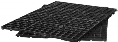
Grid element for start and end of rail, consisting of three pre-assembled units of 1 x 1.33 m each, material: recycled polyethylene; height: approximately / approx. 30 mm
| Order Nr.: | 49047 |
|---|---|
| Colour: | black |
| Length [m]: | 1.33 each |
| Material: | Recycled polyethylene |
| Width [m]: | 1.00 each |
| Height [mm]: | approximately / approx. 30 |
| Packaging unit: | 3 grid elements |
| Additional info: | The three grid elements must be assembled on site to form a start or end grid |
in accordance with DIN EN 795:2012, types D + E, as a roof-penetration-free anchor device for safety equipment for fall protection during care and maintenance work as a rail running parallel to the edge of roof / perimeter made of a high-strength aluminium alloy, which is attached at a maximum distance of 4.5 m by means of Stainless steel Connectors to plastic grid elements connected to discs and free-running and 360° rotatable anchor eye and installed according to the manufacturer's specifications. The system is secured using bulk materials approved by the manufacturer.
Superimposed / extra load for DN 0°-2° min. 110 kg/m², Superimposed / extra load for DN 2°-5° min. 130 kg/m²
The position planning must be approved by the manufacturer.
including all system components and
Assembly set consisting of type plate, Instructions for use, control cards and copper paste
Make: Zinco "Fallnet® SR Rail"
Unit: pcs
Order Nr.: 49047
Fallnet® SR Rail
Fallnet® SR Rail, in conjunction with a Superimposed / extra load of suitable bulk material (e.g. ZinCo System Substrate, Zincolit® or gravel 16/32 mm), is an anchor device in accordance with DIN EN 795:2012 types D and E for fall protection on flat roofs with a roof slope of up to 5°. An anchor point - the so-called runner - may be used simultaneously by a maximum of one person (up to 100 kg) with PPE Personal Protection Equipment (e.g. the ZinCo PPE-Set) in accordance with DIN EN 363. Harness in accordance with EN 361 may only be used with tested and approved components.
Important notice:
We would like to expressly point out that - irrespective of product liability - ZinCo only accepts liability for advice in the event that installation is carried out in accordance with our planning. Installation without planning by ZinCo is at your own risk. The Installation Instructions and the Instructions for Use, both of which are supplied with the products, must be observed regardless of this. We recommend having Fallnet® SR Rail planned or checked by the ZinCo application technology department before starting work.
1.0 Before installation
1.1 Checking the scope of delivery/condition of the system components
The scope of delivery of a Fallnet® SR Rail fall protection system assembled for a specific project essentially consists of:
A. Fallnet® SR Rail structural elements, such as
Pre-assembled grid elements of 12 individual grids each for the manufacture of grid elements AE (rail start or rail end) and grid elements M (rail center)
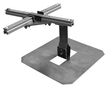
Rail support, consisting of base plate with locking tabs and stainless steel rail supports with square head screw
Rails made of a high quality aluminium alloy in standard lengths of 2.0 m, 3.0 m and 6.0 m, connectors, end pieces, runners, etc.
The required quantities and properties (z. thermal) of the structural elements can be found on the delivery bill.
B. Documents included in the scope of delivery per order:
Installation Instructions, Instructions for use and control card. The site plan sent separately to the customer (if the planning has been carried out by ZinCo GmbH) must be handed over to the client.
Attention: Incomplete, faulty or defective deliveries are to be objected to immediately.
1.2 Checking the initial situation
Before starting the installation, check whether the roof structure is sufficiently dimensioned for the loads to be applied, whether the maximum possible roof slope (5°) is not exceeded and whether waterproofing / sealing, root protection, etc. have been professionally installed. If there are any doubts, these must be clarified and, if necessary, eliminated before installation.
1.3 Permitted types of installation
The following types of installation are permitted for the installation of Fallnet® SR Rail:
A. For multi-layer structures:
Fallnet® SR Rail is positioned above the drainage level directly on the associated Filter Sheet.
B. For single-layer structures:
Fallnet® SR Rail is laid directly on the protective layer (> 300 g/m²).
1.4 Assembly of the grid elements
Grid elements consist of the structural elements:
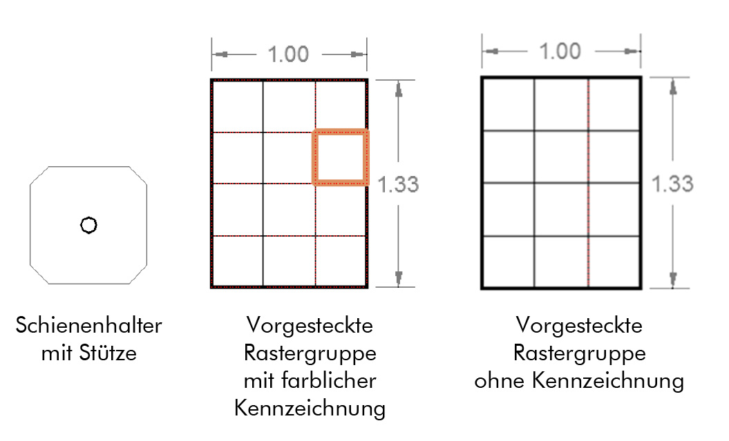
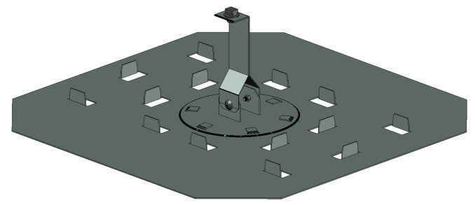
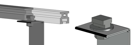
To create the friction-locked connection between the rail supports and grid elements, guide the first grid element unit over the rail support at the colored marking and snap into place with foot pressure. Attach one or two further grid element unit(s) at the start and end of the rail so that the rail support is in the center of the grid element. All grid elements of a grid element group must be engaged at the connection points and thus form a tension-distributing disc.
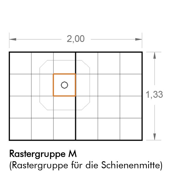
A grid element group M consists of a rail support with square head screw and two pre-attached grid elements:
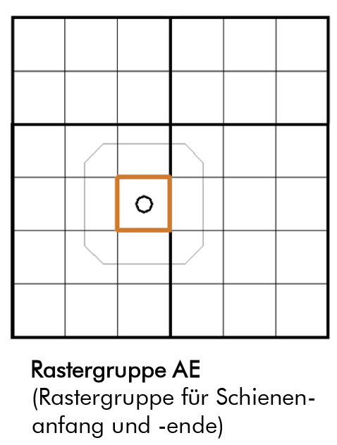
A grid element AE consists of a rail support with square head screw and three pre-attached grid elements, one of which must be split:
Important: Check the connection points between the assembled grid elements, replace damaged grids.
2.0 Installation instructions
2.1 Measuring the grid elements
Use the dimensioned planning to measure the track layout and position the grid elements AE and grid elements M. The distance between the rail supports along the track must not exceed 4.50 m. The grid elements must be permanently level and rest completely on the substrate described in 1.3.
2.2 Installing the Fixing rail
Tools required:
- Socket wrench SW 17.0
- Allen key SW 6.0
- Torque wrench
- Optional ZinCo drilling set for manufacturing rail adapters
Depending on the planning, a Fixing rail consists of:
- Rail 6 m
- Rail 3 m
- Rail 2 m
- Connector
- End piece
- corner 90° corner piece
- fallnet Junction Unit incl. column (for support)
- Runner
- Fitting piece
Each rail support is fitted with a square head screw. The rail is threaded into the T slot via this square-head screw and thus connected to the already positioned grid element.
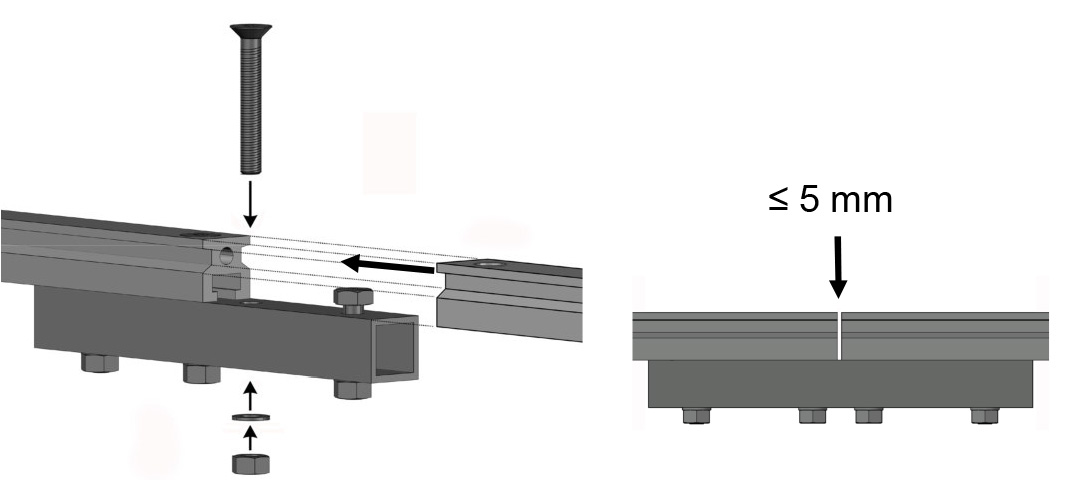
Mounting the rail on the Connector
The rail section is extended by connecting further rails using connectors. Hand-tighten the self-locking nuts (max. 20 Nm). The maximum gap of 5 mm between the rails must be observed.
Installing connectors
- Before completing the rail section, insert the anchor point (runner) into the rail.
- Necessary fitting pieces can be produced directly on site using the ZinCo drilling set (see drilling set instructions).
- Depending on the planning, a closed ring-shaped system or termination with end pieces is possible.
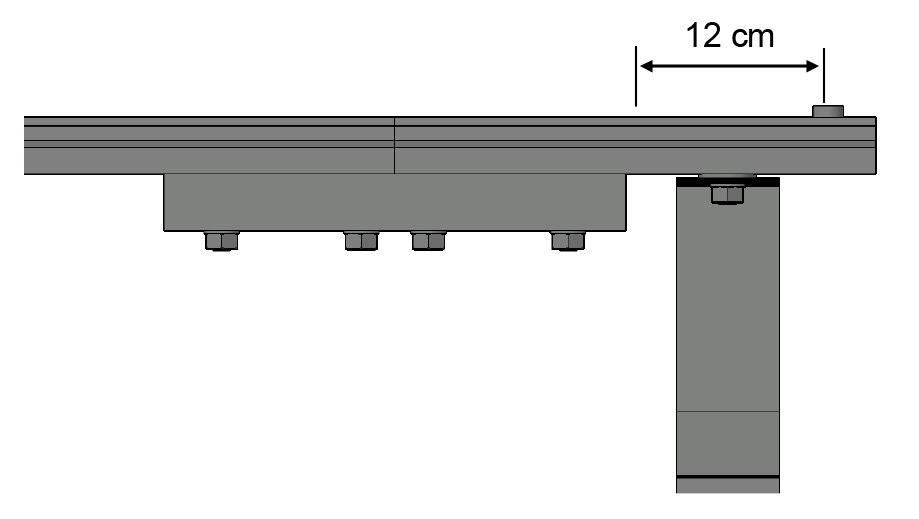
- Termination with rail end pieces:
Screw end pieces to the ends of the rail section using connectors. The end pieces are threaded over the rail support of grid element AE and fastened between the first or last butt joint connector or end piece and the stopper screw of the end pieces (clearance approximately / approx. 12 cm). A larger rail protrusion is not permitted!
Fitting the end piece
- Check the position of the rail run and the rail supports of the grid elements according to the planning and correct if necessary.
- Finally, check and tighten all screw connections.
Specifications according to DIN EN 365:
The equipment may only be used by trained persons who have been instructed in its safe use and have the relevant knowledge.
Specifications in accordance with DIN EN 795:
The anchor devices may only be installed by qualified personnel or qualified companies. It is also recommended that the anchor devices are marked with the date of the next and last inspection.
Important:
In general, the material temperature should not be below +5 °C during installation.
Adding the graphite or copper paste included in the scope of delivery prevents the stainless steel screws from "seizing".
Options for adapting to rising structural elements etc.:
- Rotating the grid elements without changing the position of the rail support
- Slippage of the grid element with rail support (observe axial dimensions max. 4.50 m!)
- By repositioning individual grids (33 cm x 33 cm), roof outlets or fans, for example, can be embedded. Make sure that the rail support is not positioned in the outermost row of grid elements.
2.3 Applying the required Superimposed / extra load
Before applying the required Superimposed / extra load, the installation situation must be documented and photographed if necessary.
Documentation
Corresponding templates can be found under Product documents at the top of this page.
The grid elements of Fallnet® SR Rail must be filled and covered evenly over the entire surface with suitable fill material. This can be done using ZinCo System Substrate, Zincolit®, 16/32 mm gravel / grit or a comparable bulk material.
Superimposed / extra load required for Fallnet® SR Rail:
min. 110 kg/m² (roof slope 0° to 2°)
min. 130 kg/m² (roof slope > 2° to 5°)
The values apply when the bulk material is dry. The layer thickness of the bulk material used depends on its bulk weight (dry). For reasons of UV protection, a gravel layer must be at least 5 cm above the top edge of the plastic grids.
Important: The grids must always be in direct contact with the Superimposed / extra load (bulk material).
3.0 Completion
Check that all work has been carried out correctly in accordance with the planning and Installation Instructions. Check the identification mark at the entry point, it must be clearly and permanently visible. Only rail systems marked with a sticker may be used.
3.1 Installation documentation
The installation documentation provides the client with proof that the installation has been carried out correctly. In addition, it is the indispensable basis for a later inspection of the Fallnet® anchor devices.
A template for the installation documentation is available as a PDF file from the manufacturer. Copies of the documentation must be handed over to the client after installation and kept on site for later inspection of the Fallnet® SR Rail.
Minimum information required:
- Address of the property
- Installation company
- Responsible fitter
- Fallnet® serial number (see runner or sticker)
- Superimposed / extra load details (which bulk material, bulk weight, enclose delivery bills if necessary)
- Installation plan (please also enter the serial number(s) there)
The installation plan should be clearly visible to everyone on the structure, e.g. at the roof exit.
Confirmation by the person responsible for installation:
- The Fallnet® installation instructions have been followed.
- Contractor as planned.
- The minimum load specifications were adhered to.
- Photo documentation, especially of details that are invisible in the final state.
3.2 Handover of the documents to the client/owner
The scope of delivery includes the following documents, which must be handed over to the client:
- Instructions for installation and use
- Installation documentation
- Inspection card, Fallnet® SR Rail must be regularly maintained and checked. Please enter serial numbers (see runner or sticker)
- Site plan
3.3 Questions
If you have any questions, are unsure about the correct use/installation of the products or would like further detailed information for your specific property, please contact the ZinCo Hotline, Phone 07022 9060-770.