
Zinco height adjustment SGR-HV made of aluminium, approx. 950 mm length
Special lower part of the frame, which is screwed fixing to the Solar Base SB 200 and into which a Solar base frame SGR is inserted from above and also screwed fixing.
for continuous height adjustment of the Solar base frame SGR used by up to 210 mm; weight approx. 1.0 kg
| Order Nr.: | 970090 |
|---|---|
| Colour: | Aluminium nature |
| Material: | Aluminum material AlMg3 |
| Length [mm]: | 950 |
| Packaging unit: | Piece |
| Weight [kg]: | 1,0 |
| Additional information: | Height: approx. 350 mm; height adjustment range: up to max. 210 mm |
Lower part made of aluminium for continuous height adjustment of the Solar base frames SGR 5 to SGR 45 from 0-210 mm. The panel slope from 5° to 45° can be changed by + 2°. Length approx. 950 mm, height approx. 350 / 430, pre-drilled for mounting the module support profiles.
Make: Zinco Solar base frame "SGR HV"
Notice: After installing the Solar base frames, the wind bracing and the solar mounting profile must be installed immediately!
Unit: pcs
Order Nr.: 970090
Installation SB 200 with SGR-HV:
Scope of delivery per unit:
1 pc. Zinco Solar Base SB 200
2 hexagonal nuts M10 with flange, A2, DIN 6923, width across flats 15 mm
2 pcs. Stainless steel washers
1 pc. Zinco Solar base frame SGR
1 pc. SGR-HV
1 pc. screw set SGR-HV
Tools required
Socket wrench SW 15
Torque wrench 20 Nm
.jpg)
Installation steps:
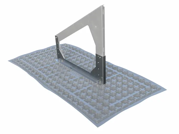
Lay out Solar Base SB 200, with pre-assembled fixing points. Place Solar base frame height adjustment SGR-HV.
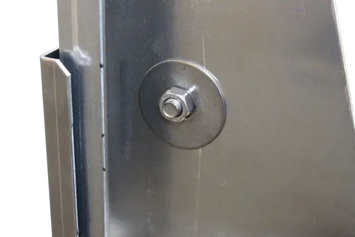
Hand-tighten screws, tightening torque > 20 Nm.
Insert the Zinco SGR Solar base frame into the SGR-HV height adjustment, adjust to the desired height and tighten the screw to 20 Nm. Height adjustment up to max. 210 mm possible.
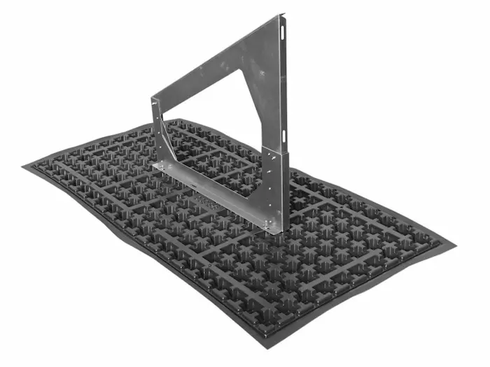
Finished Solar Base SB 200 with Solar base frame SGR and height adjustment HV.
- The material temperature should not be below +5 °C during installation.
- The entire surface of the Solar Base SB 200 must always be covered with bulk material corresponding to the required Superimposed / extra load.
- If the complete PV or thermal system is not installed immediately, the horizontal mounting profiles and wind bracing must be installed in any case.
- Due to the high dead load of thermal systems, wind bracing (WV5) must also be installed at the front.
- Always use a Stainless steel washer Ø inside/outside 10.5/20 mm when mounting horizontal profiles with M8 screws.
- No liability if the installation instructions are not followed.
Installation wind bracing:
Scope of delivery per unit:
1 set of wind bracing consists of:
2 pcs. pre-drilled aluminum flat strip rods (riveted in the middle)
4 pcs. Round head screws M8 × 16, A2, DIN 603
4 hexagonal nuts M8, A2, DIN 93
4 pcs. Stainless steel washers, Ø inside/outside 10.5/20 mm
Tools required:
Socket wrench SW 13
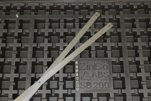
When installing the wind bracing, the positions according to the installation plan must be observed (red crosses). For installation, the wind bracing is pulled apart and screwed to the back of the frame using the four carriage bolts. The carriage bolts are inserted from the inside through the slotted holes (once at the frame high point and once at the frame low point). The screws are tightened to 8 Nm (hand-tight).
This product has accessories

Special lower part of the frame, which is screwed fixing to the Solar Base SB 200 and into which a Solar base frame SGR is inserted from above and also screwed fixing.