

Zinco grid element for Extension Segment of Fallnet SR
Additional grid element for expansion by 1.33 m²
Order Nr.:
9051
Product information "Zinco grid element for Extension Segment of Fallnet SR"
pre-attached grid elements 1.00 x 1.33 m, made of recycled polyethylene
| Order Nr.: | 9051 |
|---|---|
| Material: | Recycled polyethylene |
| Packaging unit: | 1 element |
| Weight [kg/m²]: | 6,4 |
| Additional information: | Additional grid element: 1.00 x 1.33 m |
from position '.........', consisting of interconnected
deliver and install plastic grid elements bonded together to form a single panel with a total area of 1.33 m², and install them according to the manufacturer’s specifications.
Brand: Additional grid element forFallnet® SR
Unit: pcs
Order Nr.: 9051
We expressly note that, regardless of product liability, Zinco assumes liability for consulting services only if the installation is carried out in accordance with our plans. Installation without planning by Zinco is at your own risk. Regardless of this, the Installation Instructions and user manual must be strictly followed.
Before installing the Fallnet® SR anchor device, check the following points:
0.1 Scope of delivery and condition of system components Check:
Is the delivery complete and in perfect condition?
Important:
Incomplete, incorrect, or defective deliveries must be reported immediately. The scope of delivery for each Fallnet® SR consists of:
- anchor point:

1 = Base plate with locking tabs
2 = Column (for support)
3 = Attachment eye
4 = Identification mark
- Load-bearing panel (2.00 × 2.67 m) consisting of four pre-assembled grid elements:

5 = four pre-assembled grid elements, each measuring 1.00 × 1.33 m
6 = Marking and device for the proper positioning of the single attachment point
7 = 1.00 m
8 = 1.33 m
0.2 Assessment of the Initial Situation
Before installation begins, it must be verified that the roof structure is sufficiently dimensioned for the loads to be applied, that the waterproofing / sealing and, if applicable, root protection are in place, and whether the actual substrate for the Fallnet® SR has been properly and evenly laid and has an inclination of no more than 5 degrees (= 8.8%). If there are any doubts, these must be clarified before installation. The substrate must be free of dirt, oil, algae, etc., for the installation of Fallnet® SR. The surface may need to be swept clean, for example.
0.3 General Principles
Fallnet® SR can be installed, for example:
Important:
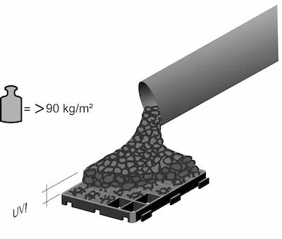
Direct contact with the superimposed / extra load (bulk material) is always required! To achieve this, the Fallnet® SR must be completely infilled with suitable bulk material and covered (UV protection!).
This can be achieved using Zincolit® or Zinco System Substrate, 16/32 mm gravel / grit, or a comparable bulk material. Installation is permitted on roofs with a roof slope of up to 5 degrees (= 8.8%)!
The required superimposed / extra load (dry weight) for the Fallnet® SR is at least 110 kg/m². This must be increased to 130 kg/m² if the roof slope exceeds 2° (3.4%) and a fall in the direction of the slope is possible.
If the Fallnet® SR is integrated into a Green Roof, a gravel strip with a width of at least 0.30 m should be provided around the anchor point to make it more easily recognizable.
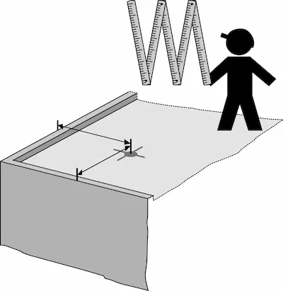
1.1 Measuring the Anchor Point
The position of the anchor point must be determined using a roof layout plan. Care must be taken to ensure that the anchor eye is at least 2.50 m away from the building edge / drop edge where a fall could occur.
1.2 Connecting the Marked Grid Element to the Anchor Point
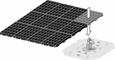
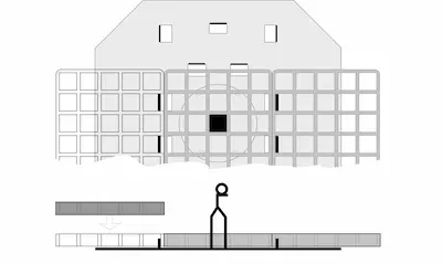
Place the centrally punched-out opening of the colored element of the pre-assembled grid element (1.00 × 1.33 m) over the anchor point and carefully snap it into place by applying pressure with your foot, so that it rests flat against the base plate and the vertical strips of the base plate engage behind the outer web of the adjacent black grid.
1.3 Positioning the grid element, including the anchor point
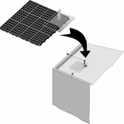
Position the grid element, including the anchor point, at the measured point (see 1.1).
1.4 Connecting the Four Grid Elements
Next, the three remaining grid elements are connected to one another so that the anchor point is located at the center of the assembled grid surface. Together, the four pre-assembled grid elements form a continuous panel of approx. 5.3 m². The Fallnet® SR must rest completely on a level surface; all connection points must be locked into place. Locked elements can be released by tapping with a hammer. Defective elements must be replaced.

1.5 Applying the Required Superimposed / Extra Load
The completed Fallnet® SR is now infilled with the superimposed / extra load (e.g., Zinco System Substrate or 16/32 mm gravel / grit) and covered; see 0.3 General Principles for requirements.
2. Adaptation to Site-Specific Conditions
Fallnet® SR offers the option of adapting the standard shape (2.00 × 2.67 m) to the structural conditions of the site, if necessary.
Schematic representation (standard):
.webp)
1 = building edge / drop edge
2 = 48 grid elements, each 0.33 × 0.33 m
3 = Base plate and fixing point
4 = Cover with loose material extending at least 500 mm beyond the grid
Schematic illustration of the standard installation of the centrally located anchor point with the four pre-installed grid elements (each 1.00 × 1.33 m).
Installation around obstacles:
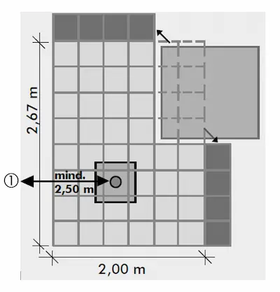
1 = Building edge / drop edge
By repositioning the individual grid elements, protruding structural elements such as vents, outlets, etc., can be accommodated. Note that the anchor point must not be positioned in the two outer rows of grid elements. In addition, the anchor point must be positioned centrally within a grid element (0.33 × 0.33 m). In the direction of load, there must be at least 20 grid elements behind the anchor point. It is recommended that such non-standard installation of Zinco be planned or reviewed by Zinco.
3.1 Completion, identification mark
Ensure that all work has been performed properly and that the identification mark is clearly and permanently visible. Only anchor devices marked with a label may be used.
3.2 Installation Documentation
The installation documentation serves as proof to the client that the installation was performed properly. Furthermore, it serves as an indispensable basis for a subsequent inspection of the Fallnet® anchor device(s). A template for the installation documentation is available from the manufacturer as a PDF file. Copies of the document must be provided to the client upon completion of installation and retained at the site for future inspection of the Fallnet®.
Before installing the Fallnet® SR anchor device, check the following points:
0.1 Scope of delivery and condition of system components Check:
Is the delivery complete and in perfect condition?
Important:
Incomplete, incorrect, or defective deliveries must be reported immediately. The scope of delivery for each Fallnet® SR consists of:
- anchor point:
1 = Base plate with locking tabs
2 = Column (for support)
3 = Attachment eye
4 = Identification mark
- Load-bearing panel (2.00 × 2.67 m) consisting of four pre-assembled grid elements:
5 = four pre-assembled grid elements, each measuring 1.00 × 1.33 m
6 = Marking and device for the proper positioning of the single attachment point
7 = 1.00 m
8 = 1.33 m
0.2 Assessment of the Initial Situation
Before installation begins, it must be verified that the roof structure is sufficiently dimensioned for the loads to be applied, that the waterproofing / sealing and, if applicable, root protection are in place, and whether the actual substrate for the Fallnet® SR has been properly and evenly laid and has an inclination of no more than 5 degrees (= 8.8%). If there are any doubts, these must be clarified before installation. The substrate must be free of dirt, oil, algae, etc., for the installation of Fallnet® SR. The surface may need to be swept clean, for example.
0.3 General Principles
Fallnet® SR can be installed, for example:
- on the protective layer over the waterproofing / sealing (e.g., Zinco SSM 45 Protection Mat / Moisture Retention for single-layer greening)
- on the Filter Sheet (for a multi-layer green roof)
- Care must be taken to ensure that there are no objects (e.g., concrete slabs) in the area around the anchor point (radius of at least 0.5 m) that could prevent the column (for support) from bending as intended.
- Furthermore, ensure that the bulk material to be applied to Fallnet® SR as a superimposed / extra load extends at least 500 mm beyond the grid elements on all four sides.
Important:
Direct contact with the superimposed / extra load (bulk material) is always required! To achieve this, the Fallnet® SR must be completely infilled with suitable bulk material and covered (UV protection!).
This can be achieved using Zincolit® or Zinco System Substrate, 16/32 mm gravel / grit, or a comparable bulk material. Installation is permitted on roofs with a roof slope of up to 5 degrees (= 8.8%)!
The required superimposed / extra load (dry weight) for the Fallnet® SR is at least 110 kg/m². This must be increased to 130 kg/m² if the roof slope exceeds 2° (3.4%) and a fall in the direction of the slope is possible.
If the Fallnet® SR is integrated into a Green Roof, a gravel strip with a width of at least 0.30 m should be provided around the anchor point to make it more easily recognizable.
1.1 Measuring the Anchor Point
The position of the anchor point must be determined using a roof layout plan. Care must be taken to ensure that the anchor eye is at least 2.50 m away from the building edge / drop edge where a fall could occur.
1.2 Connecting the Marked Grid Element to the Anchor Point
Place the centrally punched-out opening of the colored element of the pre-assembled grid element (1.00 × 1.33 m) over the anchor point and carefully snap it into place by applying pressure with your foot, so that it rests flat against the base plate and the vertical strips of the base plate engage behind the outer web of the adjacent black grid.
1.3 Positioning the grid element, including the anchor point
Position the grid element, including the anchor point, at the measured point (see 1.1).
1.4 Connecting the Four Grid Elements
Next, the three remaining grid elements are connected to one another so that the anchor point is located at the center of the assembled grid surface. Together, the four pre-assembled grid elements form a continuous panel of approx. 5.3 m². The Fallnet® SR must rest completely on a level surface; all connection points must be locked into place. Locked elements can be released by tapping with a hammer. Defective elements must be replaced.
1.5 Applying the Required Superimposed / Extra Load
The completed Fallnet® SR is now infilled with the superimposed / extra load (e.g., Zinco System Substrate or 16/32 mm gravel / grit) and covered; see 0.3 General Principles for requirements.
2. Adaptation to Site-Specific Conditions
Fallnet® SR offers the option of adapting the standard shape (2.00 × 2.67 m) to the structural conditions of the site, if necessary.
Schematic representation (standard):
1 = building edge / drop edge
2 = 48 grid elements, each 0.33 × 0.33 m
3 = Base plate and fixing point
4 = Cover with loose material extending at least 500 mm beyond the grid
Schematic illustration of the standard installation of the centrally located anchor point with the four pre-installed grid elements (each 1.00 × 1.33 m).
Installation around obstacles:
1 = Building edge / drop edge
By repositioning the individual grid elements, protruding structural elements such as vents, outlets, etc., can be accommodated. Note that the anchor point must not be positioned in the two outer rows of grid elements. In addition, the anchor point must be positioned centrally within a grid element (0.33 × 0.33 m). In the direction of load, there must be at least 20 grid elements behind the anchor point. It is recommended that such non-standard installation of Zinco be planned or reviewed by Zinco.
3.1 Completion, identification mark
Ensure that all work has been performed properly and that the identification mark is clearly and permanently visible. Only anchor devices marked with a label may be used.
3.2 Installation Documentation
The installation documentation serves as proof to the client that the installation was performed properly. Furthermore, it serves as an indispensable basis for a subsequent inspection of the Fallnet® anchor device(s). A template for the installation documentation is available from the manufacturer as a PDF file. Copies of the document must be provided to the client upon completion of installation and retained at the site for future inspection of the Fallnet®.
Required minimum information in the installation documentation:
The installation plan should be posted on the structure where it is visible to everyone, e.g., near the roof hatch.
Confirmations by the person responsible for installation (signed by this person):
3.3 Handover of Fallnet® SR Documents to the Client/Owner
The following documents are included in the scope of delivery and must be handed over:
In addition, the following should be provided:
3.4 Questions
If you have any questions, are unsure about the proper use or installation of the products, or would like further, detailed information for your specific project, please contact Zinco GmbH.
- Property address
- Installation company
- Installer in charge
- Fallnet® serial numbers
- Information on the superimposed / extra load (type of bulk material, bulk weight; include delivery slip if available)
- Installation plan (please also enter the serial numbers there)
The installation plan should be posted on the structure where it is visible to everyone, e.g., near the roof hatch.
Confirmations by the person responsible for installation (signed by this person):
- The Fallnet® Installation Instructions were followed.
- Installed as planned
- The minimum load requirements were met Photographic documentation, particularly of details that will be invisible in the final state.
3.3 Handover of Fallnet® SR Documents to the Client/Owner
The following documents are included in the scope of delivery and must be handed over:
- Installation and Instructions for use
- Inspection card. Please enter the serial number(s) of the Fallnet®. You will find these on the identification mark directly on the product. Fallnet® SR must be inspected regularly. (You will receive one inspection card per product, but you may list all serial numbers for a single construction project on a single inspection card.)
In addition, the following should be provided:
- Installation documentation
- Site plan
3.4 Questions
If you have any questions, are unsure about the proper use or installation of the products, or would like further, detailed information for your specific project, please contact Zinco GmbH.
This product is accessories from

Additional grid element for expansion by 1.33 m²
Zinco Fallnet SR, anchor device with grid elements 2.00 x 2.67 m
Superimposed / extra load anchor device in accordance with DIN EN 795:2012 type E. Single anchor point for short-term work with PPE Personal Protection Equipment (e.g. ZinCo Fallnet® PPE-Set, Order No. 9024) on flat roofs with a maximum roof slope of 5°.
Superimposed / extra load anchor device in accordance with DIN EN 795:2012 type E. Single anchor point for short-term work with PPE Personal Protection Equipment (e.g. ZinCo Fallnet® PPE-Set, Order No. 9024) on flat roofs with a maximum roof slope of 5°.